Voltage divider for oscilloscope 1 100. The simplest oscilloscope from the computer
Oscilloscope is a tool that has almost every radio amateur. But for beginners it is too expensive.
The problem of high cost is solved simply: there are many options for making an oscilloscope.
The computer is perfectly suitable for such rework, and its functionality and appearance Not affected.
Device and purpose
The scheme of the oscilloscope is complex for understanding the novice radio amateur, so it is not necessary to consider it entirely, but after combating individual blocks:
Each block is a separate chip, or fee.
The signal from the test device comes through the Y input to the input divider, which specifies the sensitivity of the measuring circuit. After passing pre-amplifier And the delay line it falls on the final amplifier, which controls the vertical deflection of the indicator beam. The higher the signal level - the more the beam deflects. So the channel of the vertical deviation is arranged.
The second channel - horizontal deviation, is needed to synchronize the beam with a signal. It allows the beam in the specified settings place.
Without synchronization, the beam pops up over the border of the screen.
Synchronization is three species: from an external source, from the network and from the signal under study. If the signal has a constant frequency, it is better to use synchronization from it. As an external source, a laboratory signal generator is usually served. Instead, for these purposes, a smartphone is suitable with a special application installed on it, which modulates the pulse signal and displays it to the headphone socket.
Oscilloscopes are used when repairing, designing and configuring various electronic devices. This includes diagnostics of car systems, troubleshooting in household appliances and much more.
Oscilloscope measures:
- Signal level.
- His shape.
- The rate of increasing pulse.
- Amplitude.
It also allows you to deploy a signal to thousandths of a second and browse it in the smallest details.
Most oscilloscopes have a built-in frequency.
Oscilloscope connected via USB
There are many options for making homemade USB oscilloscopes, but not all of them are available to beginners. The easiest option will be its assembly of ready-made components. They are sold in radio markets. Cheaper option will buy these radio components in Chinese online stores, but you need to remember that components purchased in China can come in a faulty state, and money for them is not always returned. After the assembly, a small prefix connecting to the PC should be.
This option of oscilloscope has the highest accuracy. If a problem arises, which oscilloscope choose to repair laptops and other complex equipment, it is better to stop your choice on it.
For the manufacture you will need:
- Board with dated paths.
- CY7C68013A processor.
- Microcircuit analog-digital converter AD9288-40BRSZ.
- Capacitors, resistors, chokes and transistors. Ratings of these elements are indicated on the schematic diagram.
- Soldering hairdryer for sealing SMD components.
- Wire in a varnish insulation by a cross section of 0.1 mm².
- Toroidal core for winding the transformer.
- A piece of fibercristolite.
- Soldering iron with ground sting.
- Solder.
- Flux.
- Soldering paste.
- EEPROM FLASH 24LC64 memory microcircuit.
- Case.
- USB connector.
- Socket for connecting probe.
- TX-4.5 relay or other, with a control voltage of no more than 3.3 V.
- 2 AD8065 operating amplifiers.
- DC-DC converter.
You need to collect on this scheme:
Typically, for the manufacture of printed circuit boards, radio amateurs use the etching method. But thus make a double-sided pCB With a complex layout, it will not work independently, so it needs to be ordered in advance at the factory producing such fees.
To do this, you need to send a drawing of the board to the factory, according to which it will be produced. At the same plant make different card quality. It depends on the options selected when ordering.
In order to get a good fee in the end, you need to specify in order the following conditions:
- The thickness of the fiberglass is not less than 1.5 mm.
- The thickness of the copper foil is at least 1 oz.
- Through metal holes.
- The suspension of contact platforms by a lead-containing solder.
After receiving the finished board and buying all radio components, you can start assembling an oscilloscope.
The first is the DC-DC converter, outstanding voltage +5 and -5 volts.
It needs to be collected on a separate board and connect to the main with using shielded cable.
Diving chips to the main board must be carefully, not overheating. The soldering iron temperature should not be higher than the three hundred degrees, otherwise the soldered parts will fail.
After installing all components, a device is collected into a suitable housing and connected to a USB cable computer. Close Jumper JP1.
You need to install and run on the PC Cypress Suite program, go to the EZ CONSOLE tab and click on LG EEPROM. In the window that appears, select the firmware file and press ENTER. Wait for the appearance of the inscription Done, speaking about the successful completion of the process. If Error appeared instead of it, it means that an error occurred at some stage. You need to restart the flasher and try again.
After the firmware made with your own hands, the digital oscilloscope will be fully ready for operation.
Autonomous Power Option
At home, radio amateurs usually use fixed devices. But sometimes there is a situation where you need to repair something far away from home. In this case, you will need a portable oscilloscope with autonomous food.
Prepare before starting assembly the following components:
- Unnecessary Bluetooth Headphones or Audio Module.
- Tablet or smartphone on Android.
- Lithium-ion battery size 18650.
- Holder for him.
- Charge controller.
- Jack jack 2.1 x 5.5 mm.
- Connector for connecting measuring probe.
- Probs themselves.
- Switch.
- Plastic box from a sponge for shoes.
- Shielded wire with a cross section of 0.1 mm².
- Clock button.
- Termocles.
It is necessary to disassemble the wireless headset and get a control board from it. Dip the microphone from her, the power button and battery. Post down fee on the side.
Instead of Bluetooth headphones, you can use a Bluetooth audio module.
Knife scrape from the box residual sponge and clean it well using detergents. Wait until it dries, and cut holes under the button, switch and connectors.
Shut off wires to sockets, holder, button and switch. Set them into place and secure the thermoclaim.
Wires need to be connected as showing the scheme:
Decoding designations:
- Holder.
- Switch.
- Contacts "BAT + and BAT -.
- Charge controller.
- Contacts "In + and" In -.
- Jack 2.1 x 5.5 mm connector.
- Contacts "Out + and" Out -.
- Battery contacts.
- Control board.
- Contacts Power on button.
- Clock button.
- Nest for probe.
- Microphone contacts.
Then download the application of a virtual oscilloscope from the playmarket And install it on your smartphone. Turn on the bluetooth module and synchronize it with your smartphone. Connect the crates to the oscilloscope and open its software part on the phone.
When the source of the signal source is touched on the Android device screen, a curve appears, showing the signal level. If it does not appear, it means that an error was made somewhere.
You should check the connection and serviceability of the internal components. If everything is in order, you need to try to start the oscilloscope again.
Installation in the monitor housing
This version of the self-made oscilloscope is easily installed in the housing of the desktop monitor. Such a solution allows you to save a little space on your desktop.
For the assembly will be needed:
- Computer LCD monitor.
- DC-DC inverter.
- Motherboard from the phone or tablet with HDMI outlet.
- USB connector.
- A piece of hdmi cable.
- Wire with a cross section of 0.1 mm².
- Clock button.
- Resistor for 1 com.
- Double sided tape.
Integrated with your own hands in the monitor, the oscilloscope will be able to every radio amateur. First you need to remove the back cover from the monitor and find a place to install motherboard. After it was determined with the place, next to it you need to cut in the hole housing for the button and USB connector.
The second end of the cable must be soldered to the board from the tablet. Before soldering each vein, it is nicknamed by a multimeter. This will help not to confuse the order of their connection.
Next step You need to fall from the tablet board the power button and Micro USB connector. To the clock button and the USB socket solder the wires and secure them in the cut holes.
Then connect all the wires as it is shown in the figure, and solder them:
Put the jumper between GND and ID contacts in micro YUSB connector. It is necessary to translate the USB port to OTG mode.
You need to glue the inverter and motherboard from the tablet to two-way tape, and then slide the monitor cover.
Connect K. USB port. Mouse and press the power button. While the device is loaded, turn on the Bluetooth transmitter. Then need synchronize it with a receiver. You can open the oscilloscope application and make sure the device collected.
Instead of the monitor, the old LCD TV, in which there is no smart TV is perfect. The filling from the tablet in its capabilities is superior to many Smart TV systems. It is not necessary to limit its use alone with an oscilloscope.
Manufacture of audio card
The oscilloscope collected from an external audio adapter will cost only $ 1.5-2 and will take a minimum of time on its manufacture. In size, it will turn out no more than the ordinary flash drive, and the functionality will not give way to his big fellow.
Required details:
- USB audio adapter.
- Resistor for 120 com.
- MINI JACK 3.5 mm plug.
- Measuring probes.
It is necessary to disassemble the audio adapter, for this it is worth a hint and shut down the halves of the case.
Run the C6 capacitor and solder the resistor in its place. Then install the board back to the housing and collect it.
Cut the standard plug from the probe and solder the mini jack to its place. Connect the probes to the audio input audio adapter.
Then you need to download the appropriate archive and unpack it. Insert a map into a USB connector.
The simplest thing remains: go to the device manager and in the "Audio, game and video devices" tab find a connected USB audio adapter. Click on it right mouse button and select the "Update Driver" item.
Then move miniscope.exe files, miniscope.ini and miniscope.log from the archive to a separate folder. Run "miniscope.exe".
Before use, the program needs to be configured. The required settings are shown in the screenshots:
If you touch the source of the signal source, curve should appear in the oscilloscope window:
So to turn audio adapter in oscilloscopeYou need to make a minimum effort. But it is worth remembering that the error of such an oscilloscope is 1-3%, which is clearly not enough to work with complex electronics. It is perfect for a novice radio amateur, and craftsmen and engineers should be closed to other, more accurate oscilloscopes.
Homemade oscilloscopes cease to be rare as microcontrollers develop. And naturally arises the need for a dipstick for him. Preferably with a built-in divider. Some of the possible designs are discussed in this article.
The probe is assembled on a segment of foil fiberstolite and placed in a metal tube that runs the role of the screen. In order not to cause emergency situations when and if the probe falls on the test device included, the tube is covered with a heat shrink. Without covering, the blank looks like this:

Property in a disassembled form:

Designs can be different. Just need to take into account some things:
- If you perform the probe without a divider, i.e. It does not contain large resistance and switches, i.e. Elements exposed to electromagnetic tips, then appropriately shielded wire of probe stretching to the needle itself. In this case, additional screening of the items will not be needed and the dipstick can be performed from any dielectric. For example, use one of the probes for the tester.
- If a divider is performed in the probe, when you take it in your hands, you will inevitably increase the tipping and interference. Those. This will require shielding of divider elements.
In my case, the tube connection with the screen (more precisely with the reverse side of the fiberstolite) is made by soldering the springs on the tektolite, which creates a contact between the screen and the probe board.
As a needle used "PANE" from the SDC connector. But it can be performed from any other suitable rod. The connector from SHR is convenient because its "mom" can be soldered into a clamp that can be needed to wear on the dipstick.
Selection of wire
Separate mention deserves selection of wires. The correct wire looks like this:

Minijack 3.5 mm is located near the scale
The correct wire is a more or less common shielded wire, with one significant difference - the central lived alone. Very thin and made of steel wire, or even a wire with high resistivity. Why exactly I will explain a little later.
Such a wire is not very common and find it quite difficult. In principle, if you do not work with high frequencies of about a dozen megahertz, a special difference, using the usual shielded wire, you can and do not feel. I met that at frequencies below 3-5 MHz, the selection of the wire is not critical. I can not confirm nor refute - there is no practice at frequencies above 1 MHz. In what cases it can also tell you later.
Homemade oscilloscopes infrequently have a bandwidth into several megahertz, so use that wire that will find. Just strive to choose the one who has central veins of the fond and smaller. I met the opinion that the central lived should be thickening, but it is clearly from the series of "harmful councils." Small resistance of the oscilloscope wire without need. There are currents in nanoasper.
And it is important to understand the lower the own capacity of the probe manufactured, the better. This is due to the fact that when you connect the probe to the device under study, thereby connect an additional container.
If you connect directly to the output of the logical element or in the UPS, i.e. To a fairly powerful source of a signal having enough small resistance, then everything will be displayed normally. But if there are significant resistance in the circuit, the tank of the probe will strongly distort the signal form, since will be charged through this resistance. And this means that you will no longer be confident in the reliability of the oscillogram. Those. The lower the own tank of the probe, the wider the range of possible applications of your oscilloscope.
Property concepts
The actual scheme of the probe, which I applied is extremely simple:

This is a divider at 10 for an oscilloscope with 1 meg input resistance. Resistance is better to make up several connected in series. The switch simply closes directly adding resistance. A rapid condenser allows you to match the probe with a specific device.
Perhaps the more correct scheme that would be recommended to be recommended:

It is clearly better at permissible tension, since the breakdown voltage of resistors and CDD capacitors is usually taken for 100 volts. I met the allegations that they withstand 200-250 volts. Did not check. But if you explore enough high-voltage chains, it is worth applying exactly such a scheme.
A little promised theory
The capacity is directly proportional to the area of \u200b\u200bconductors and is inversely proportional to the distance between them. There is still a coefficient, but for us it is not important now.
We have two conductors. Central lives and screen wires. The distance between them is determined by the diameter of the wire. The area of \u200b\u200bthe screen will not reduce much. Yes, and no need. It remains to reduce the surface area of \u200b\u200bthe central core.
Those. Reduce its diameter as technically advisable without loss of mechanical strength.
Well, in order to increase this strength, when a diameter decreases, you need to choose the material.
The wire can be represented as:

Distributed capacity over the length of the wire. Well, the more the specific resistance of the material of the central core, the lower the influence of the neighboring sites (adjacent capacity) will provide each other. Therefore, a wire with high resistivity is appropriate. For the same reason, it is impractical to make the probe wire too long.
I will not consider the connectors. Just say that I consider the BNC connectors optimal for the oscilloscope. They are most often used. Minijack, an audio jack I would not apply to apply (although I myself apply, due to the fact that we do not use the oscilloscope in the chains with significant voltages). He is dangerous. They jerked the wire when conducting research with good tension. What happens next? And then the minijack, gliding along the nest, can cause a closure. And even if nothing happened because of various reasons, this voltage will be present on the minijack. And if he falls to your knees? And there is open central contact and land near ...
For more information, you can learn from the article cycle. So, the theory was pushed, now
Property number 2.
It is good because it can be inserted like this:

Or so, it is indifferent to him, he turns freely.

It works like this:

The only thing that will still be done on it. A hole for the exit of the Earth's wire from the probe will be flooded with a drop of thermoclaus, so that it is more difficult to snatch it with a random jerk and the wire will be fixed in the handle by a segment of the match, sharpened under a gentle wedge.

In order not to break and not unscrew the central core. By the way, this is the easiest way to "treat" cheap Chinese probe for the tester so that the wire is not broken from the tip.

What is worth paying attention to: the screen comes to almost the tip itself. It should not be under the fingers of a significant area of \u200b\u200bthe open area of \u200b\u200bthe central core, otherwise you will admire the floods from the hands on the donkey display.

Especially for the site of Radioshem - Trishin A.O. Komsomolsk-on Amur. August 2018
Discuss an article homemade probe for an oscilloscope
It is no secret that novice radio amateurs do not always have an expensive measuring equipment at hand. For example, an oscilloscope, which even in the Chinese market, the cheapest model costs about several thousand.
Oscilloscope is needed to repair various schemes, checking the amplifier distortion, sound equipment settings, etc. Very often, the low-frequency oscilloscope is used when diagnosing sensors in the car.
In this number, the simplest oscilloscope made from your personal computer will help you. No, your computer does not have to disassemble and refine. You will need only to solder the console - divider, and connect it to a PC through the audio entrance. And to display the signal to install a special software. Here for a couple of tens of minutes you will have your own oscilloscope, which may well be consolidated to analyze signals. By the way, you can use not only a stationary PC, but also a laptop or netbook.
Of course, such an oscilloscope with a large stretch is comparable to a real device, as it has a small frequency range, but the thing in the farm is very useful to see the output of the amplifier, various pulsations of power supplies and TP.
Scheme consoles
Agree that the scheme is incredible simple and will not require a lot of time for its assembly. This divider is a limiter that protects the sound card of your computer from a dangerous voltage, which you can accidentally fall on the entrance. The divider can be 1, by 10 and 100. Variable resistor The sensitivity of the whole scheme is regulated. The prefix is \u200b\u200bconnected to the linear input of the PC sound card.Collect the prefix
You can take boxing from batteries like me or another plastic case.
Software
The oscilloscope program will visualize the signal filed to the audio card input. I will offer you for downloading two options:1) A simple program without installation with a Russian interface, download.
(Dropping: 9893)

2) And the second with the installation, it can be downloaded -.

What to use - choose to you. Take and install both, and choose there.
If you already have a microphone installed, then after installing and starting the program, the sound waves can already be observed that enter the microphone. It means everything is OK.
To the console, no drivers will need no longer.
Connect the prefix to linear or microphone entrance Sound card and use on health.

If you have never had experience in working with an oscilloscope, I sincerely recommend that you repeat this homemade and work with such a virtual device. The experience is very valuable and interesting.
How to make a digital oscilloscope from a computer with your own hands?
Beginning radio amateurs are dedicated!
How to collect the simplest adapter for a software virtual oscilloscope suitable for use in repairing and configuring audio equipment. https: // Site /
The article also describes how you can measure the input and output impedance and how to calculate the attenuator for a virtual oscilloscope.
The most interesting videos on YouTube
Close themes.
About virtual oscilloscope.

Once I had a Fix idea: sell an analog oscilloscope and buy him to replace the digital USB oscilloscope. But, in the market, it discovered that the most budget oscilloscopes "begin" from $ 250, and the reviews about them are not very good. More serious devices are more than more than more.
So, I decided to restrict ourselves to an analog oscilloscope, and to build some kind of plots for the site, use a virtual oscilloscope.
I downloaded several program oscilloscopes from the network and tried to measure something, but nothing is possible from this out of this, as it was not possible to calibrate the device, or the interface was not suitable for screenshots.

It was, already threw this thing, but when I looked for myself a program for removing the frequency response, I came across the Audiotester software set. I did not like the analyzer from this kit, but the oscilloscope "Ossi" (hereinafter I will call it "Audiotester") turned out to be just right.
This device has an interface similar to a conventional analog oscilloscope, and the screen has a standard grid that allows you to measure the amplitude and duration. https: // Site /
Of the disadvantages, some instability of work can be called. The program sometimes hangs in order to reset it have to resort to the help of Task Manager. But, all this is compensated by the usual interface, ease of use and some very useful functions that I have not met in any other program of this type.
Attention! The set of "Audiotester" programs has a low frequency generator. I do not recommend using it, as it is trying to independently manage the driver of the audio card, which can lead to an irreversible audio disconnection. If you decide to use it take care of the recovery point or about backup OS. But, it is better to download a normal generator from "additional materials".

Other interesting program of virtual oscilloscope "Avangard" wrote our compatriot of records O.L.
This program has no usual measuring mesh, and the screen is too large to remove screenshots, but there is a built-in voltmeter of amplitude values \u200b\u200band the frequency meter, which partially compensates the above disadvantage.
Partly because at small levels of the signal and the voltmeter and the frequency meter begin to brave a lot.
However, for a novice radio amateur, who is not used to perceiving the plots in volts and milliseconds for division, this oscilloscope can be quite combined. Another useful property of the oscilloscope "AVANGARD" is the possibility of independent calibration of two existing scales of the built-in voltmeter.
So, I will tell you how to build a measuring oscilloscope based on the programs "Audiotester" and "Avangard". Of course, in addition to these programs, there will be any built-in or separate, the fiscal audio card.
Actually, all work is reduced to make a voltage divider (attenuator), which would allow to cover a wide range of measured stresses. Another function of the proposed adapter is to protect the entry of the audio file from damage when entering input high voltage.
Technical data and scope.
Since there is a separator capacitor in the input circuits, the oscilloscope can be used only with "closed input". That is, only the variable component of the signal can be observed on its screen. However, with some skill, with the help of the oscilloscope "Audiotester" can be measured and the level of constant component can be measured. This can be useful, for example, when the multimeter countdown time does not allow to fix the amplitude voltage value on the condenser, charged through a large resistor.
The lower limit of the measured voltage is limited to the noise level and the background level and is approximately 1MB. The upper limit is limited only by the parameters of the divider and can reach hundreds of volts.
The frequency range is limited by the capabilities of the audio card and for budgetary audio photographers is: 0.1Hz ... 20 kHz (for a sinusoidal signal).
Of course, we are talking about a pretty primitive device, but in the absence of a more advanced device, this can well be consolidated.
The device can help repair audio equipment or used for training purposes, especially if it is supplemented by a virtual LC generator. In addition, using a virtual oscilloscope it is easy to save the Eppura to illustrate any material, or to accommodate on the Internet.
Electrical circuit of the oscilloscope hardware.

The drawing shows the hardware of the oscilloscope - "adapter".
To build a two-channel oscilloscope, you will have to duplicate this scheme. The second channel can be useful for comparing two signals or to connect external synchronization. The latter is provided in the "Audiotester-E".
Resistors R1, R2, R3 and RVX. - Voltage divider (attenuator).
R2 and R3 resistor ratings depend on the applied virtual oscilloscope, or rather from the scale used by them. But, since the "Audiotester-A" price of division 1, 2 and 5, and in Avangard-A, the built-in voltmeter has only two scales related to the 1:20 coefficient, the use of an adapter assembled according to the above The scheme should not deliver inconvenience in both cases.
The input resistance of the attenuator is about 1st megoma. In a good way, this value would be constant, but the design of the divider would be more seriously complicated.
Condensors C1, C2 and C3 equalize the amplitude-frequency response of the adapter.
Stabilians VD1 and VD2 together with R1 resistors protect the linear input of the audio cards from damage in case of random high voltage to enter the adapter input when the switch is in position 1: 1.
I agree that the scheme presented is not distinguished by elegance. However, this circuit solution allows the easiest way to achieve a wide range of measured stresses when using only multiple radio components. The attenuator, built according to the classic scheme, would require the use of high-size resistors, and its input resistance would have changed too much when switching the ranges, which would limit the use of standard oscillographic cables calculated on the input impedance 1m.
Protection against "fool".

To protect the linear input of the audio cards from the random high voltage hit, parallel to the input is installed VD1 and VD2 stabilions.

The R1 resistor limits the stabilion current to 1ma, at a voltage of 1000 volts at the inlet 1: 1.
If you, indeed, are intended to use an oscilloscope to measure voltage up to 1000 volts, then as a resistor R1 you can install MLT-2 (binary) or two MLT-1 (monovatte) resistor in series, as the resistors differ not only by power, but also By maximum allowable voltage.
Condensor C1 should also have a maximum allowable voltage of 1000 volts.

Small explanation of the above. Sometimes it is necessary to look at the variable component of a relatively small amplitude, which, however, has a large constant component. In such cases, it should be borne in mind that only a variable component of the voltage can be seen on the screen of the oscilloscope with a closed input.
The picture shows that with a constant component of 1000 volts and a variable variable of a component of 500 volts, the maximum voltage applied to the input will be 1500 volts. Although, on the oscilloscope screen, we will see only a 500 volt sinusoid amplitude.
How to measure the output resistance of linear output?
This paragraph can be skipped. It is designed for lovers of small details.
The output resistance (output impedance) of a linear output designed to connect phones (headphones), too little to have a significant impact on the accuracy of the measurements that we have to be performed in the next paragraph.
So why measure the output impedance?
Since we will use a virtual low-frequency generator to calibrate the oscilloscope, then its output impedance will be equal to the line output impedance (Line Out) audio card.
Making sure that the output impedance is small, we can prevent rough errors when measuring the input impedance. Although, even with the worst coincidence, this error is unlikely to exceed 3 ... 5%. Frankly, it is even less than a possible error of measurements. But, it is known that errors have a "dial" habit.
When using a generator for repair and configuration of audio equipment, it is also desirable to know its internally resistance. This can be useful, for example, when measuring ESR (Equivalent Series Resistance) of an equivalent sequential resistance or simply reactive resistance of capacitors.
To me, thanks to this measurement, it was possible to identify the lowest output in my audio card.

If the audio card has only one output socket, then everything is clear. It is both linear output and phone numbers (headphones). Its impedance is usually small, and it can not be measured. These audio outputs are used in laptops.

When there are six more nits and there is also a couple on the front panel of the system unit, and each jack can be assigned a specific function, the output resistance of the noddes can differ significantly.
Usually, the lowest impedance corresponds to a gas jack that is default and is a linear output.
An example of identifying the impedance of several different outputs of the audiopartes set to "Phones" and "Linear Output" mode.

As can be seen from the formula, the absolute values \u200b\u200bof the measured voltage of the role are not played, because these measurements can be made long before calibration of the oscilloscope.
Example calculation.
U1 \u003d 6 divisions.
U2 \u003d 7 divisions.
RX \u003d 30 (7 - 6) / 6 \u003d 5 (OM).
How to measure the input impedance of linear input?
To calculate the attenuator for a linear entry of the audio player, you need to know the input resistance of the linear input. Unfortunately, to measure the input resistance with the help of a conventional multimeter cannot be. This is due to the fact that in the input chains of the audio clocks there are separation capacitors.
The input resistance of different audiocrats can be very different. So, this measurement will still have to do.
To measure the input impedance of the Audocarts by variable current, you need to apply to the input via a ballast (added) sinusoidal resistor with a frequency of 50 Hz and calculate the resistance according to the above formula.
The sinusoidal signal can be formed in the NC software generator, the reference to which is in "additional materials". Measurement of amplitude values \u200b\u200bcan also be made by software oscilloscope.

The picture shows a diagram of connections.
Voltages U1 and U2 need to be measured by a virtual oscilloscope in the corresponding positions of the SA switch. The absolute voltage values \u200b\u200bare not needed, so the calculations are valid to calibrate the device.
Example calculation.
Rx \u003d 50 * 100 / (540 - 100) ≈ 11.4 (com).
Here are the results of measurements of the impedance of different line inputs.
As you can see, the input resistances differ at times, and in one case almost an order.
How to calculate the voltage divider (attenuator)?
The maximum unlimited amplitude of the audio drive input voltage, with a maximum recording level, about 250mB. The divider of tension, or as it is also called, the attenuator allows you to expand the range of measured oscilloscope stresses.
The attenuator can be built according to different schemes, depending on the division coefficient and the necessary input resistance.
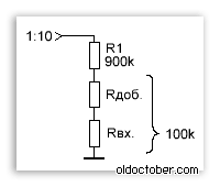
Here is one of the variants of the divider to make the input resistance to a multiple of ten. Thanks to the addition resistor RDB. You can adjust the resistance of the lower shoulder of the divider to some round value, for example, 100 com. The disadvantage of this scheme is that the sensitivity of the oscilloscope will be too much dependent on the input resistance of the audio circuit.
So, if the input impedance is 10 kΩ, then the division division coefficient will increase ten times. Reduce the top shoulder resistor of the divider is not desirable, since it determines the input resistance of the device, and is the main link to protect the device from high voltage.

So, I suggest you independently calculate the divider, based on the input impedance of your audio card.
There is no mistake in the picture, the divider begins to divide input voltage Already when choosing a scale of 1: 1. Calculations, of course, you need to do, relying on the real ratio of the shoulder of the divider.
In my opinion, this is the simplest and at the same time the most universal divider scheme.


Example of calculating the divider.
Source values.
R1 - 1007 com (the result of measuring the resistor on 1 MΩ).
RVX. - 50 com (I chose a higher input of two on the front panel of the system unit).
Calculation of the divider in the position of the 1:20 switch.
First calculate the formula (1) of the division division coefficient determined by resistors R1 and RVX.
(1007 + 50)/ 50 = 21,14 (time)
So, the overall division factor in the 1:20 switch position should be:
21,14*20 = 422,8 (time)
We calculate the value of the resistor for the divider.
1007*50 /(50*422,8 –50 –1007) ≈ 2,507 (com)
The calculation of the divider in the 1: 100 switch position.
We define the overall fission ratio in the position of the 1: 100 switch.
21,14*100 = 2114 (time)
We calculate the size of the resistor for the divider.
1007*50 / (50*2114 –50 –1007) ≈ 0,481 (com)
To facilitate the calculations, look at this link:
If you are going to use only the oscilloscope "Avangard" and only in ranges 1: 1 and 1:20, the accuracy of the resistor selection may be low, since the "avant-garde" can be calibrated independently in each of the two available ranges. In all other cases, there will have to pick up resistors with maximum accuracy. How to do this is written in the next paragraph.

If you doubt the accuracy of your tester, you can adjust any resistor with a maximum accuracy of the comparison method of an ohmmeter.
For this, instead of a constant resistor R2 temporarily installed a rapid resistor R *. The resistance of the trim resistor is selected so as to obtain a minimum error in the corresponding division range.
The resistance of the trimmed resistor is then measured, and the constant resistor is already adjusted under the resistance measured by an ohmmeter. Since both resistors are measured by the same instrument, the error of the Ommeter does not affect the accuracy of the measurement.

And this is a couple of formulas for calculating the classic divider. A classic divider can be useful when high input resistance of the device (MΩ / B) is required, and I do not want to use an additional divisory head.
How to pick up or adjust the resistors of the voltage divider?
Since the radio amateurs often experience difficulties in the search for precision resistors, I will talk about how you can adjust the usual wide-use resistors with high accuracy.
High-precision resistors are just a few times more expensive, but they sell them 100 pieces on our radio launch, which makes them buying not very expedient.
The use of trimming resistors.

As you can see, each shoulder of the divider consists of two resistors - permanent and trimmed.
The disadvantage is cumbersome. Accuracy is limited only to the available accuracy of the measuring instrument.
Selection of resistors.

Another way is the selection of steam resistors. Accuracy is ensured by selecting pairs of resistors from two sets of resistors with large scattering. First, all resistors are dimly, and then pairs are selected, the sum of the resistance of which is most complied with the scheme.
It is this way that in an industrial scale, a divisor resistors for the legendary TL-4 tester were caught.
The lack of the method is the complexity and need for a large number of resistors.
The longer the list of resistors, the higher the selection accuracy.
Fitting resistors with emery paper.

Fitting resistors, by removing a part of the resistive film, even the industry does not happen.
However, when fitting high-level resistors is not allowed to cut through the resistive film through. At high-resistant film resistors MLT, the film is applied to a cylindrical surface in the form of a spiral. Such resistors need to be supported extremely careful not to break the chain.
An accurate fit of resistors in amateur conditions can be carried out with the help of the small emery paper - "zero".

First, with a mlt resistor, which has obviously smaller resistance, the protective layer of paint is neatly removed using a scalpel.

The resistor is then falling to the "ends" that are connected to the multimeter. Careful movements of the skins - "zero" resistance of the resistor is communicated to the norm. When the resistor is fitted, the location of the cut is covered with a layer of protective varnish or glue.
What is the skin - "Nullet" is written.
In my opinion, this is the fastest and easiest way, which, however, gives very good results.
Construction and details.

The elements of the adapter scheme are placed in a rectangular duralumin case.
Switching the fission coefficient of the attenuator is carried out by a toggle switch with the middle position.

The standard CP-50 connector is applied as the input jack, which allows the use of standard cables and probes. Instead, you can apply the usual Jack type audio jack (Jack) 3.5mm.
Output connector - standard audio socket 3.5mm. The adapter is connected to the linear input of the audio card with a cable with two jacks 3.5mm at the ends.

The assembly is made by mounted mounting.

To use the oscilloscope, you will need another cable with a dipstick at the end.
Oscilloscope is a device that helps to see the dynamics of oscillations. With it, you can diagnose various breakdowns and get the necessary data in electronics. Previously, oscilloscopes on transistor lamps were used. These were very cumbersome devices that were connected exclusively to the built-in or designed specifically for them.
Today, devices for removing the main frequency, amplitude characteristics and forms of the signal are convenient portable and compact devices. Often they are performed as a separate console connected to a computer. This mannewer allows you to remove the monitor from the configuration, significantly reduced the cost of the equipment.
What a classic device looks like can be seen by considering the photo of the oscilloscope in any search engine. At home, it is also possible to mount this device using inexpensive radio components and housings from other equipment for a more presentable type.

How can I get an oscilloscope
Equipment can be paid in several ways and it all depends exclusively on the amount of money that can be spent on the purchase of equipment or parts.


- Buy a finished device in a specialized store or order it on the network;
- Buy designer, for example, wide popularity now enjoy radio components, enclosures that are sold on Chinese sites;
- Self assemble a full-fledged portable device;
- Mount only the console and probe, and the connection is to organize to a personal computer.
These options are given in order to reduce equipment costs. Buying a ready-made oscilloscope will cost more than just because it has already been delivered and a working block with all the necessary features and settings, and in case of incorrect work, you can contact the sales center.

The designer includes a simple oscilloscope scheme with his own hands, and the price is reduced due to payment only by the cost of radio components. In this category, it is also necessary to distinguish between more expensive and simple software and functionality of the model.

The assembly of the device itself according to the available schemes and acquired at different points of radio components may not always be cheaper than the acquisition of the designer, so it is necessary to preliminarily evaluate the cost of the venture, its justification.

The cheapest way to get the oscilloscope will turn only the prefix to it. For the screen, use the computer monitor, and the removal and transformation programs of the resulting signals can be downloaded from different sources.


Oscilloscope Designer: Model DSO138
Chinese manufacturers have always been famous for the ability to create electronics for professional needs with very limited functionality and for quite small money.

On the one hand, such devices are not able to fully satisfy a number of human needs engaged in radio electronics in a professional bed, but beginners and lovers of such "toys" will be more than enough.

One of the popular models of Chinese production such as an oscilloscope designer is considered to be DSO138. First of all, this device has a low cost, and it is supplied with the whole set of necessary parts and instructions, so how to make the oscilloscope, with your own hands, using the documentation of the questions, it should not occur.

Before installation, you need to get acquainted with the contents of the package: the board, screen, probe, all the necessary radio components, instructions for the assembly and the schematic diagram.

Facilitates the availability of almost all parts and the board of the appropriate labeling, which really turns the process into picking up the children's designer with adults. In the diagrams and instructions, all the necessary data is clearly visible and you can figure out, not even owning a foreign language.


At the output there must be a device with such characteristics:
- Input voltage: DC 9V;
- Maximum input voltage: 50 VPP (1: 1 Property)
- Current consumption 120 mA;
- Signal band: 0-200KHz;
- Sensitivity: Electronic displacement with the option of vertical adjustment 10 mV / cases - 5V / DIV (1 - 2 - 5);
- Discrete frequency: 1 MSPS;
- Input resistance: 1 m;
- The time interval: 10 μs / div - 50s / div (1 - 2 - 5);
- Accuracy of measurements: 12 bits.

Step-by-step instruction assembly designer DSO138
It should be considered in more detail detailed instructions For the manufacture of oscilloscope of this brand, after all, the assembly of other models is being built.

It is worth noting that in this model, the board comes immediately with a 32-bit 32-bit kernel on the M3 Cortex ™ microcontroller. It works two 12-bit inputs with a 1 μs characteristic and operates in the maximum frequency range up to 72 MHz. The presence of this device already mounted slightly facilitates the task.

Step 1. It is more convenient to start mounting with sMD components. It is necessary to take into account the rules when working with a soldering iron and a fee: do not overheat, keep not longer than 2 seconds, not torture different parts and tracks, use soldering paste and solder.

Step 2. Space capacitors, chokes and resistance: You need to insert the specified part in the place allotted on the board for it, cut off the excess leg length and searched on the board. The main thing is not to confuse the polarity of the capacitors and do not silence the soldering iron or the adjacent tracks.


Step 3. Mount the remaining details: Switches and connectors, buttons, LED, quartz. Particular attention should be paid to the side of diodes and transistors. Quartz has a metal in its structure, therefore it is necessary to ensure the absence of direct contact of its surface with the pathways or take care of the dielectric lining.

Step 4. 3 connector solder to the display board. After completion of manipulations with a soldering iron, you need to rinse with alcohol without auxiliary means - no rolling, disks or napkins.

Step 5. Seeing the fee and check how qualitatively soldered. Before connecting the screen, you need to solder two jumpers to the board. This will use existing ones with details.

Step 6. To check the work, you need to turn on the device into a network with a current of 200 mA and a voltage of 9 V.

Check is to remove indicators from:
- 9 V connector;
- Control point 3.3 V.

If all parameters match the desired values, you need to turn off the power supply and install the JP4 jumper.

Shar g 7. In 3 available connector, you need to insert the display. To the input you need to connect the probe for the oscilloscope, with your own hands on the power on.

The result of the correct installation and assembly will be the appearance on the display of its number, such as firmware, its version and developer's website. After a few seconds it will be possible to observe sine waves and the scale when the probe is turned off.

Computer prefix
When assembling this simple device, you will need the minimum number of parts, knowledge and skills. The schematic diagram is very simple, unless you need to make a fee for assembling the device.

The sizes of the prefix to the oscilloscope will be about the same as the boxes for matches or a little more, so it is best to use such a size of a plastic container or battery boxing.

By placing a collected appliance with ready-made outputs into it, you can start organizing a computer monitor. To do this, download the "Oscilloscope" and "SoundCard Oscilloscope" programs. You can test their work and choose the one that I liked more.

A connected microphone can also be retransmitted to the connected oscillator sound waves, the program will reflect the changes. This prefix connects to the microphone or line input and does not require any additional drivers.

Photo oscilloscopes do it yourself

